Overview
After a recent sinus/ear infection I began to experience tinnitus. In my case it presents itself as a constant high frequency static hiss/whine in my left ear. It’s been about a month since I first noticed it. Hopefully it will eventually disappear. During the day when I’m at work or around friends I don’t really notice it. However when I’m in a quiet room, such as when falling asleep or in the early morning after waking up, it is quite noticeable and distracting.
I found that playing white noise found on various Spotify playlists (this one is my current favourite) as I fall asleep helps mask the hiss in my ear.
So to help me fall asleep and relax in the bedroom I put together a remote control capable Arduino-based white noise player, using the Adafruit Wave Shield and an IR receiver from SparkFun. This allows me to use my phone to watch Netflix or YouTube, whilst still having the white noise play in the background.

Features
- Plays audio files from an SD card in an endless loop
- Remote control volume adjust
- Remote control mute
- LED activity indicator
- USB powered, using a micro USB connecter
- Power on/off with toggle switch.
Components
- Arduino UNO R3
- Adafruit Wave Shield
- IR Remote Control
- SparkFun IR Receiver Breakout
- Pololu USB Micro-B Breakout
- A plastic enclosure box
- A small speaker
- A red LED
- A toggle switch
Generating White Noise With Audacity
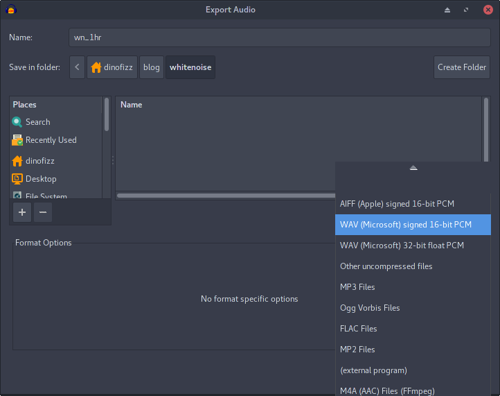
The Adafruit Wave Shield plays audio files from an SD card. I am using just one audio file, an hour long recording of white noise I generated using Audacity. The audio file needs to be in a specific format (uncompressed 16 bit, mono, 22050 Hz) to be readable by the Wave Shield. Here I describe how this file was generated and saved.
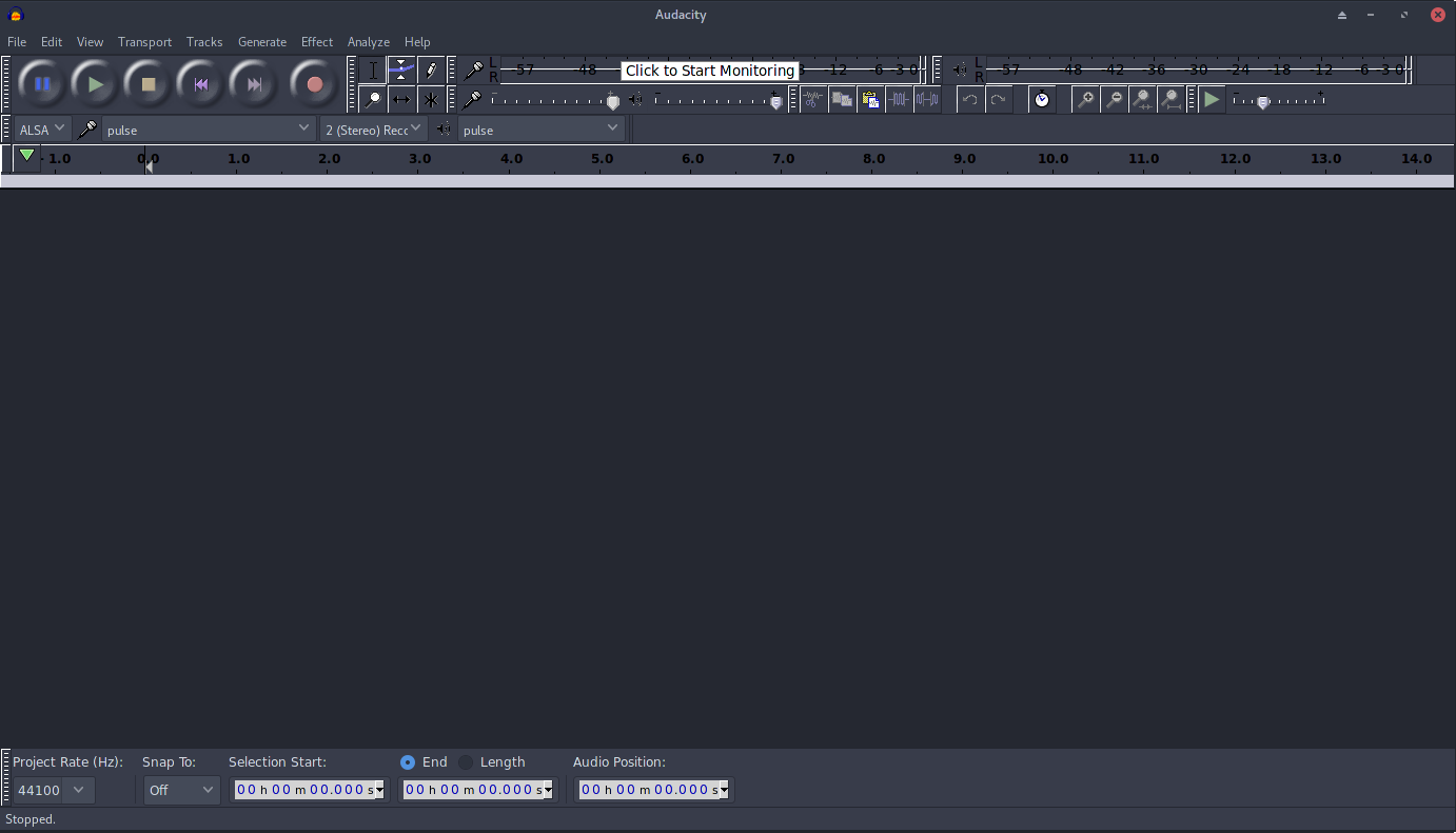
Open Audacity
Excuse the dark UI theme in my screenshots, it will look different on different operating systems/desktop environments.
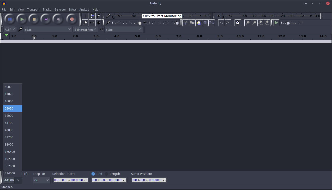
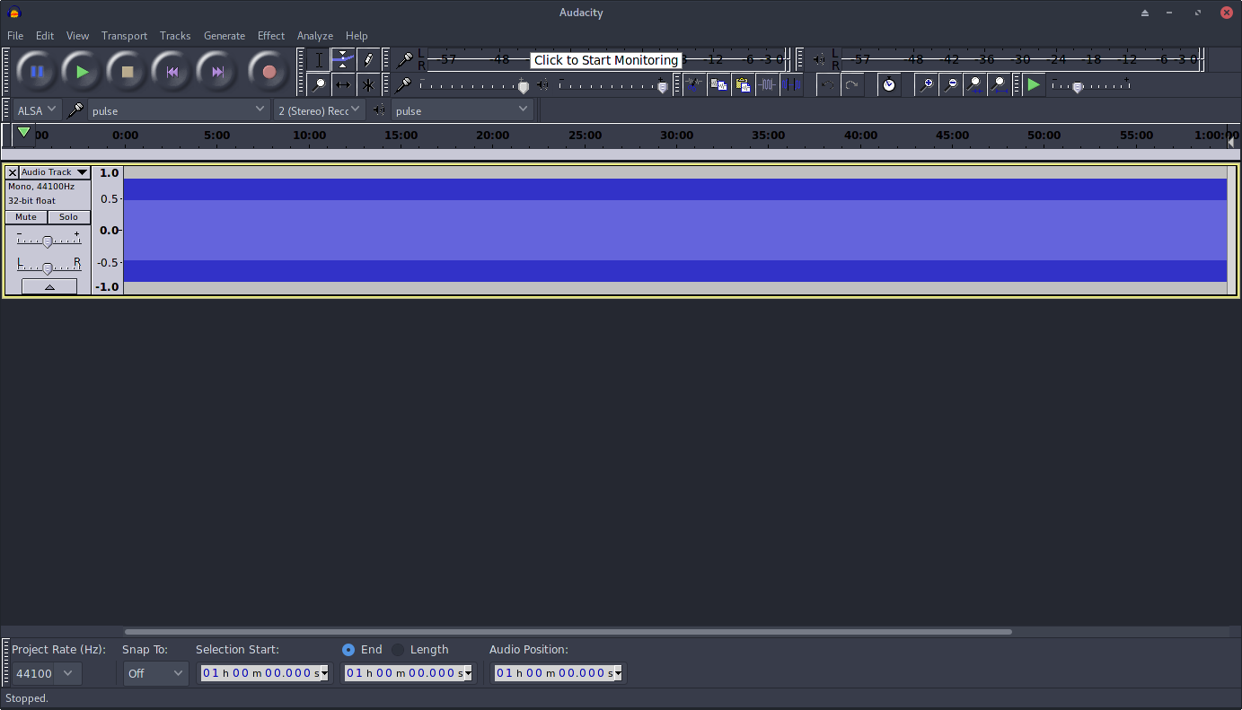
Change the Project Sample Rate
Click drop down on the bottom left of the screen to change the project rate from 44100 Hz to 22050 Hz.
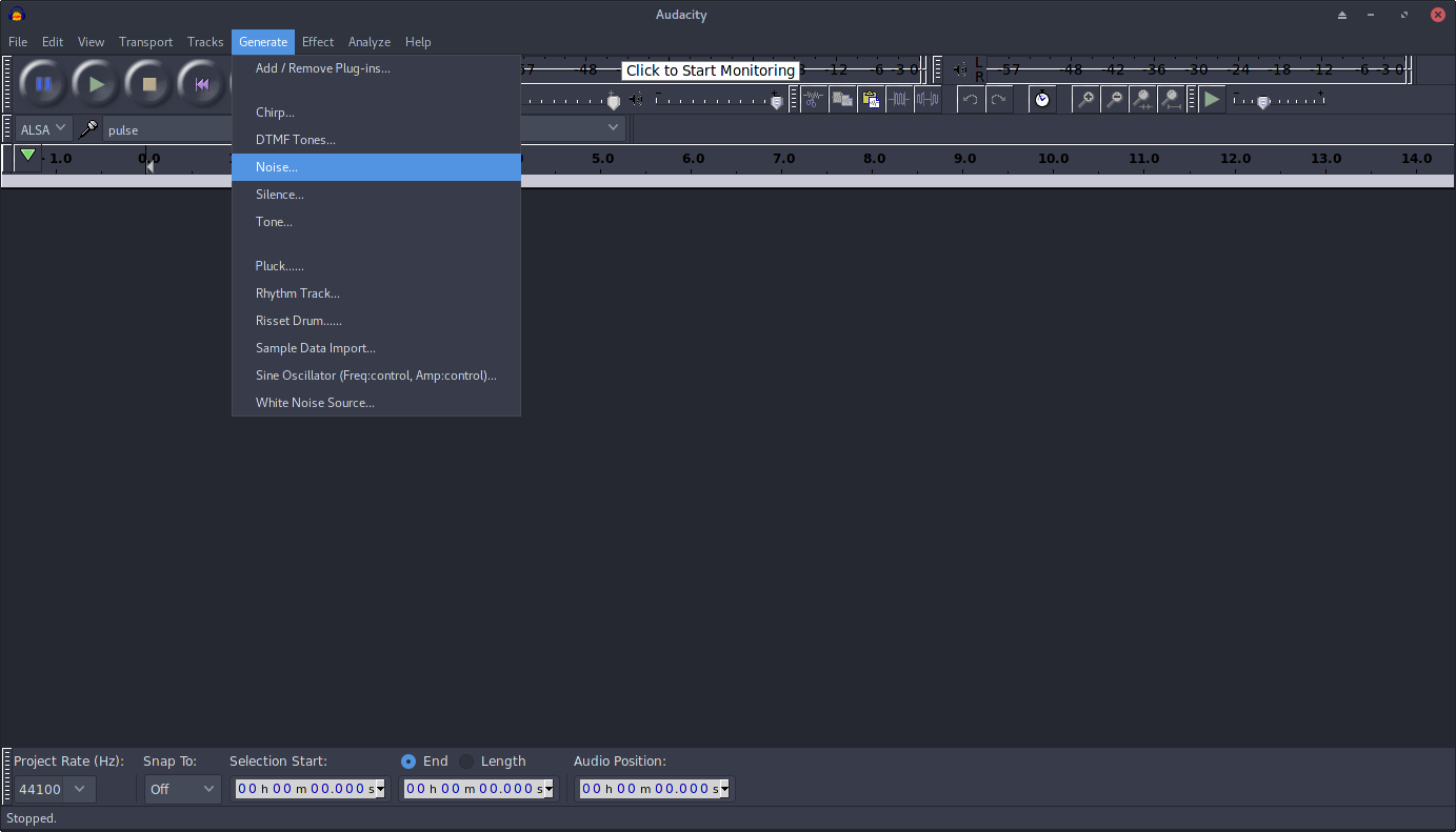
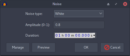
Generate White Noise
Click the “Generate” menu option and select “Noise…”
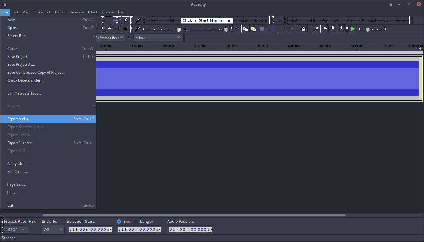
Export the Audio
You are now ready to export this Audacity project to a format that is playable on the Wave Shield. Select the export option from the File menu.
Arduino Libraries
The latest version of the Arduino IDE includes a library manager, which makes it easy to import the required libraries for this project.
You will need the “WaveHC” library for operation of the Wave Shield, and the “IRremote” library for decoding the IR signal from the remote control.
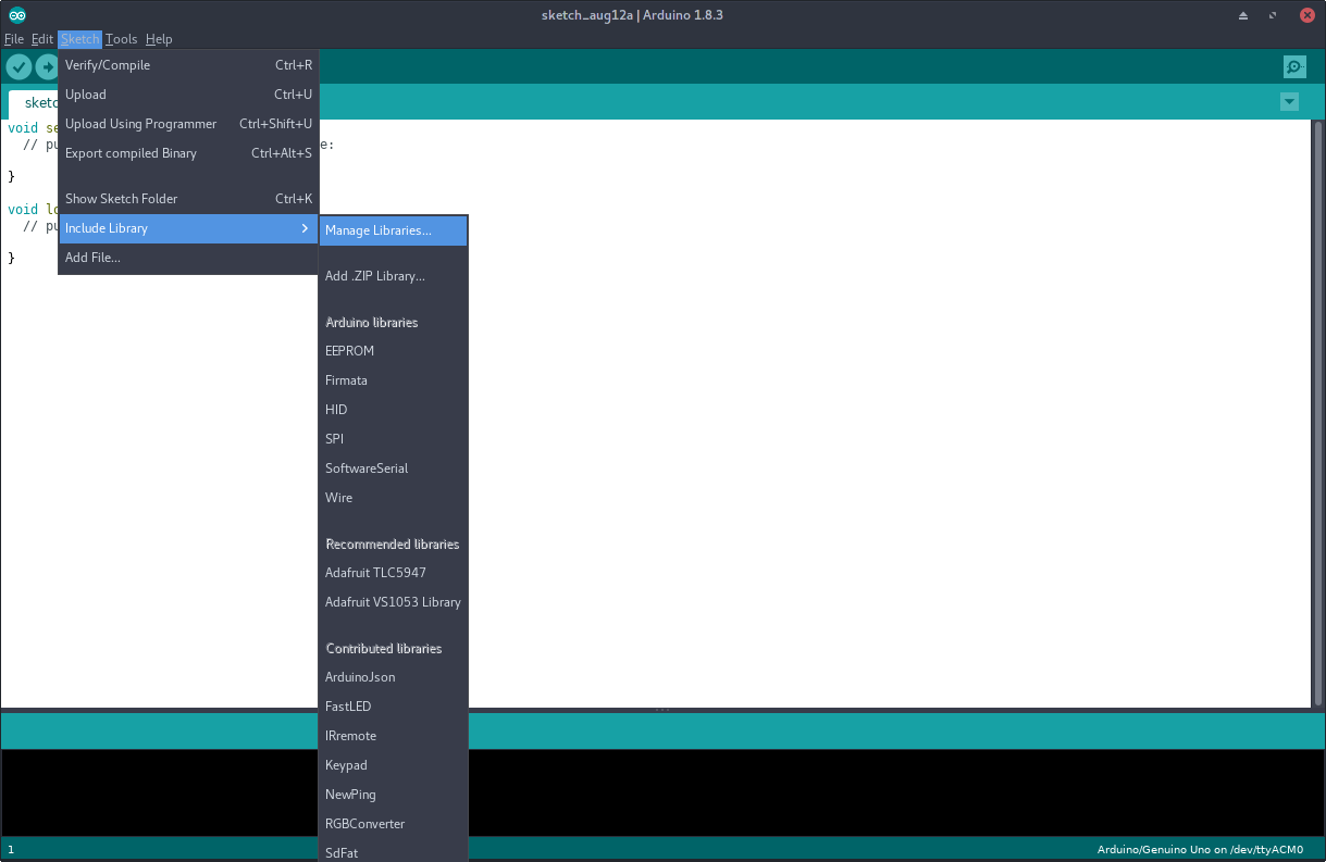
To install the libraries, open the Arduino IDE, click “Sketch” -> “Include Library” -> “Manage Libraries…”
From the library manager you should search for and install the latest versions of the following libraries:
- WaveHC by Adafruit (GitHub link)
- IRremote by shirrif (GitHub link)
Adafruit Wave Shield
I won’t go into much detail on assembling and getting the Wave Shield working, as there is a comprehensive tutorial available directly from Adafruit:
https://learn.adafruit.com/adafruit-wave-shield-audio-shield-for-arduino/overview
Follow all the instructions and make sure you can play audio files from the SD Card.
Here is a short video of the Wave Shield playing my white noise file:
Software Volume Control
The Wave Shield itself uses a large round potentiometer to allow for manual control of the output volume. However I wanted to control the volume remotely, without needing to turn the volume wheel. Adafruit provide a sample Arduino sketch which makes use of software volume control to adjust the volume: https://github.com/adafruit/WaveHC/blob/master/WaveHC/examples/SoftVolumeHC/SoftVolumeHC.pde
The comment at the top of this sketch reads:
/*
 * DVOLUME must be set nonzero in WaveHC.h to use this example.
 *
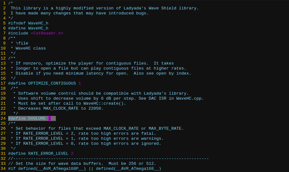
To change the value of DVOLUME you will need to find the location of WaveHC.h. On my system it is found at ~/Arduino/libraries/WaveHC/WaveHC.h.
Modify the line #define DVOLUME 0 so that it is changed to #define DVOLUME 1:
You might want to upload and run the SoftVolumeHC sketch to test that your changes were made correctly.
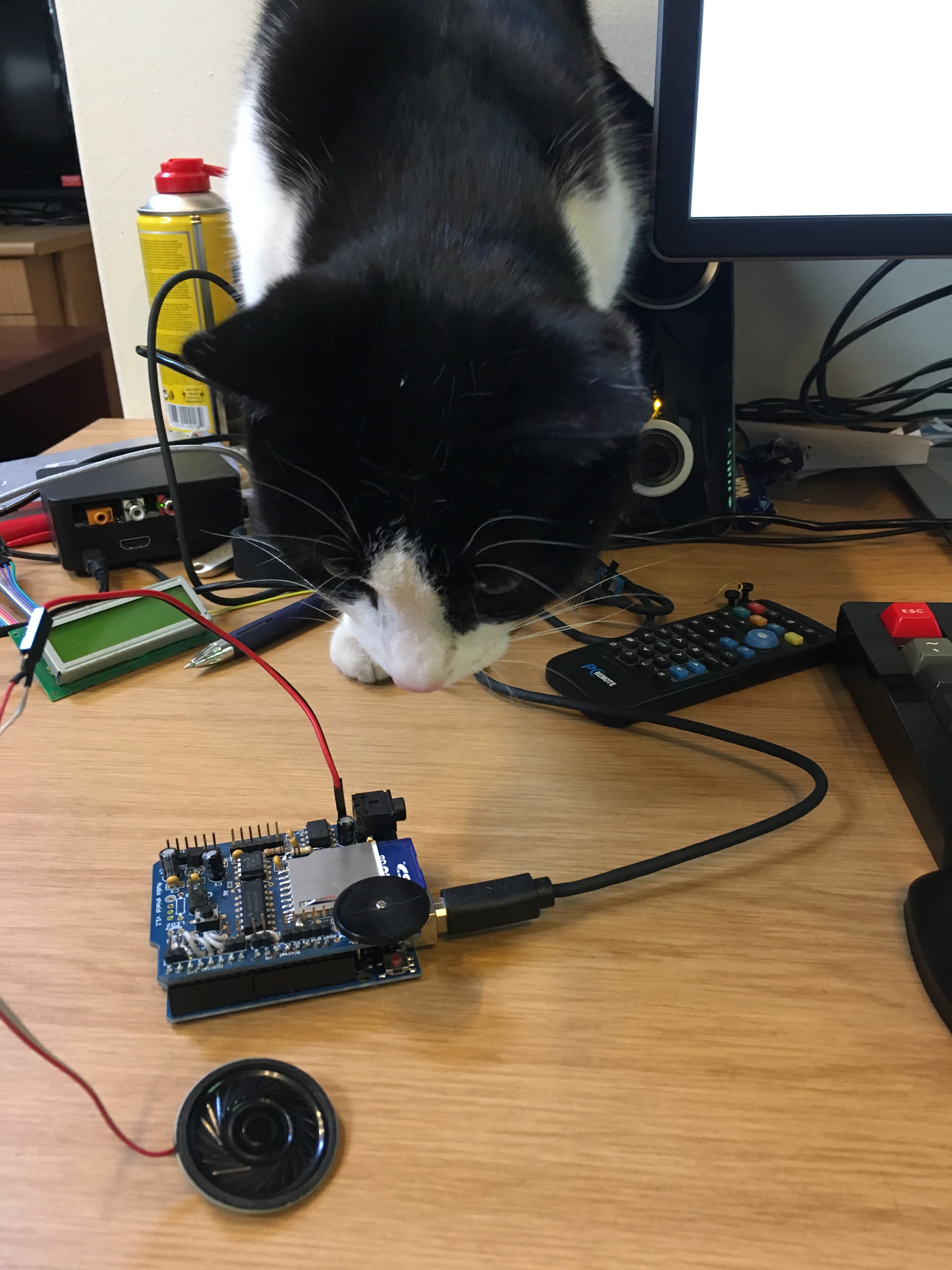
Infrared Remote Control
To provide the remote control functionality I am using a infrared (IR) “PC Remote” which I purchased a while ago to use with a Raspberry Pi. It comes with an USB IR receiver, but I won’t be using that.
To receive IR signals on the Arduino I am using an IR receiver module from SparkFun. SparkFun currently lists this product as “retired”. I bought a bunch a few years ago, and haven’t needed to use one until now! It looks like this product should just about do the same job.
Almost all consumer electronics which use IR remote control do so using a 38 kHz modulation scheme. SparkFun has a great tutorial covering IR basics here.
Capture the Codes
To change and mute the volume for this white noise player you need to be able to read the IR codes sent from the remote on the various button presses, and match them with some hard-coded values in our Arduino sketch which represent the intended action.
The Arduino IRremote library that was installed in an earlier step contains IR codes for many consumer electronics brands, such as SONY, PANASONIC, LG. Unfortunately it does not contain the codes for my “PC Remote”.
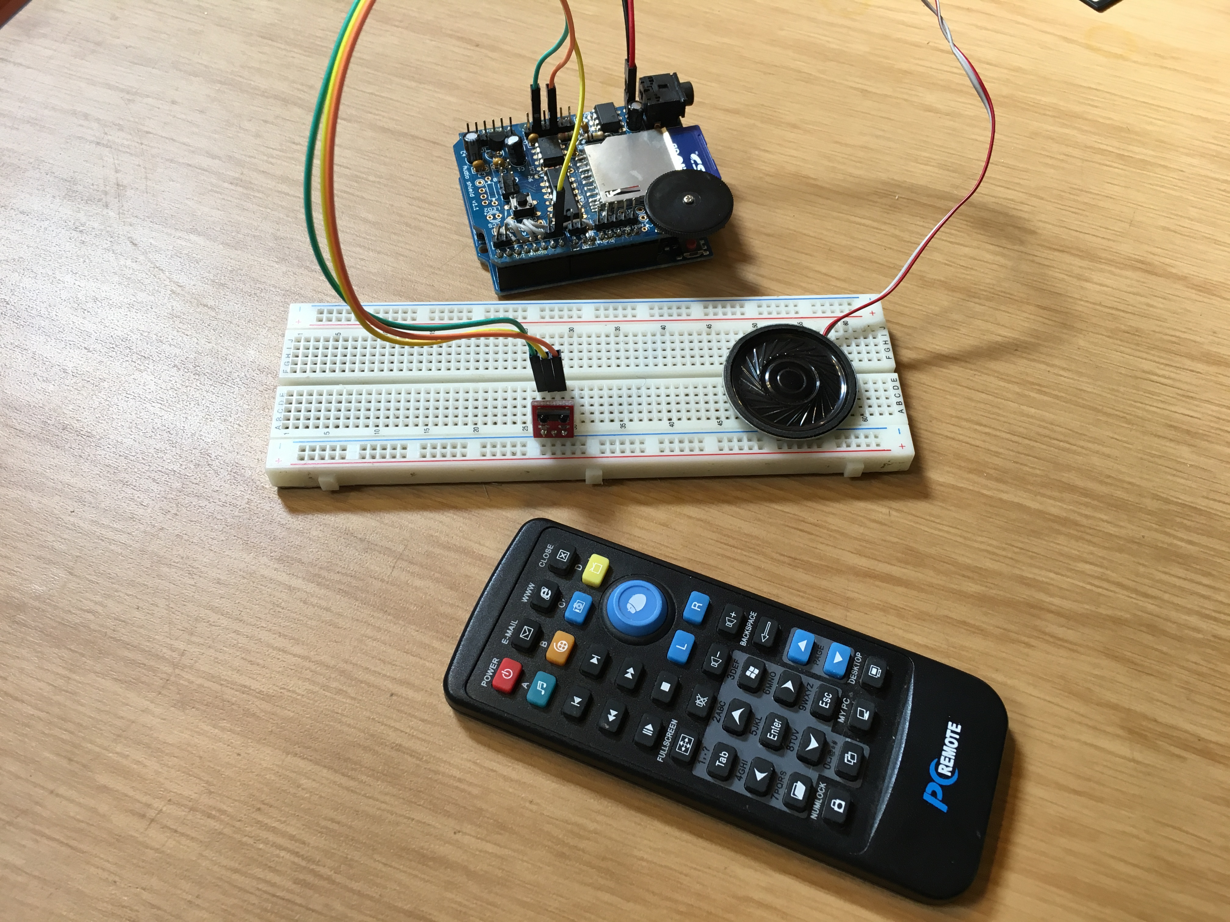
Determining which button sends which exact code is done by wiring up the IR receiver to the Arduino and loading this “IR Recorder” sketch to the Arduino. The IR receiver needs 3 connections:
- VCC to the Arduino’s 5V supply
- GND to the Arduino’s GND supply
- OUT to one of the Arduino’s digital pins (in my sketch I am using pin 11)
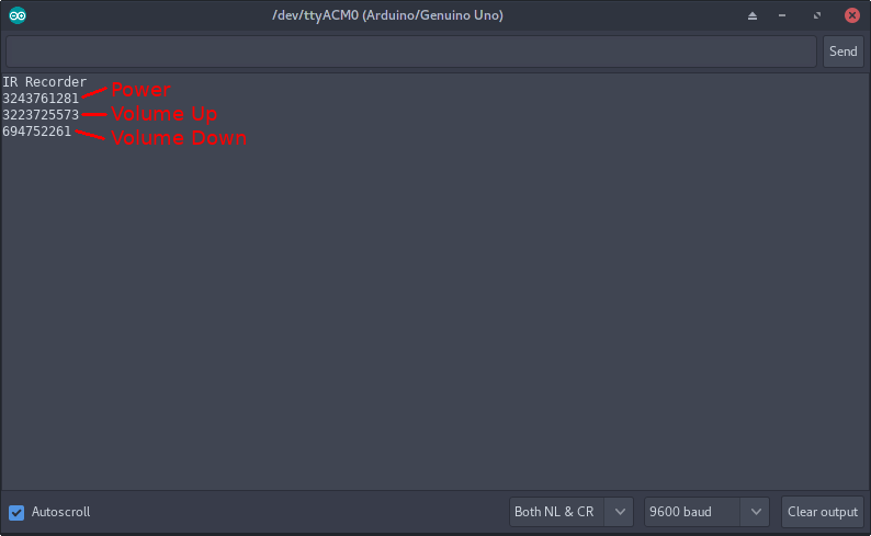
Once the sketch has been uploaded, you can run the Serial Monitor from the Arduino IDE to view any incoming IR codes, which are printed out as integers. I simply pointed my “PC Remote” at the receiver and recorded the various numbered codes for various buttons. For NoiseBlanket I am really only interested in the codes for the “Power” button and “Volume Up” and “Volume Down”.
Now that I have the Wave Shield working and the IR receiver codes for PC Remote I can put everything together!
NoiseBlanket Arduino Sketch
The sketch running on the Arduino is a modified version of one of the WaveHC library sample sketches: daphc.pde
The “daphc.pde” sketch simply plays every compatible .WAV file that it can find on the SD card in an endless loop. If you wish to learn more about the operation of the WaveHC library I recommend you read through the sketch’s source code, as it contains many comments which explain the setup of the Wave Shield and how the files are read from the SD card.
A great feature of the WaveHC library is that it plays the audio “asynchronously” with respect to the Arduino’s main loop. This allows one to do other things with the Arduino while the audio is playing.
For my sketch I modified a portion of the “play” method to continuously read from the IR receiver, and when matching IR codes are found the intended action is performed. Currently the sketch handles the following three codes:
POWER- Integer IR code received:
3243761281 - Mutes/un-mutes the audio playback.
- Integer IR code received:
VOLUME_UP- Integer IR code received:
3223725573 - Increases the volume of audio playback.
- Integer IR code received:
VOLUME_DOWN- Integer IR code received:
694752261 - Decreases the volume of audio playback.
- Integer IR code received:
My sketch can be found on my GitHub page here.
Here is a snippet of the sketch which shows the handling of the IR codes:
Note that the WaveHC software volume control implementation uses a value for 0 as the maximum volume MAX_VOLUME, with positive integer values representing lower volume levels. A volume level of 12 represents the lowest volume level MIN_VOLUME.
...
while (wave.isplaying) {

    activityBlink();

    if (irrecv.decode(&results)) {
    unsigned long ir_result = results.value;

    switch (ir_result) {
        case VOLUME_UP:
        if (volumeLevel > MAX_VOLUME && volumeLevel != MIN_VOLUME) {
            wave.volume--;
            volumeLevel--;
        }
        break;
        case VOLUME_DOWN:
        if (volumeLevel < MIN_VOLUME && volumeLevel != MIN_VOLUME) {
            wave.volume++;
            volumeLevel++;
        }
        break;
        case POWER:
        if (volumeLevel != MIN_VOLUME) {
            storedVolume = volumeLevel;
            wave.volume = MIN_VOLUME;
            volumeLevel = MIN_VOLUME;
        }
        else {
            wave.volume = storedVolume;
            volumeLevel = storedVolume;
        }
        break;
        default:
        break;
    }

    blink(1, 200); // [Dino] Blink to indicate we did receive something.
    irrecv.resume();
    }

    delay(100);
}
...
You will notice that the statements tracking and adjusting the volume control are seemingly “doubled”. I need to modify the WaveHC library wave object’s volume, as well as keep a local variable volumeLevel updated with the same volume level. This is because the wave object is created anew for each file playback, and the initial volume after object creation is set to be the maximum volume. So I set each new wave object’s volume to be that of the my local volumeLevel value to preserve volume levels between tracks. (I suppose I could also be saving the volume level at the end of track playback and restoring it when the new wave object is created).
I have added some helper functions for the LED activity light:
blinkwill repeat a flash of an LED for a specified number of repetitions and duration.errorLoopwill flash the LED repeatedly indefinitely.activityBlinkforces a single blink of the LED every 10 seconds.
...
/*
  Helper function which blinks the LED the specified number of times for the
  specified duration.
*/
void blink(uint8_t repetitions, uint16_t delay_duration) {
  for (int i = 0; i < repetitions; i++) {
    digitalWrite(LED_PIN, HIGH);
    delay(delay_duration);
    digitalWrite(LED_PIN, LOW);
    delay(delay_duration);
  }
}

/*
  Helper function which blinks the LED at a rapid pace, endlessly.
*/
void errorLoop() {
   while (1) {
    blink(10, 100); // [Dino] Blink rapidly to indicate something went wrong.
  }
}

/*
  Blinks the activity LED once every ACTIVITY_INTERVAL_MILLIS.
*/
void activityBlink() {
  unsigned long currentMillis = millis();
  unsigned long deltaMillis = currentMillis - savedMillis;

  if (deltaMillis > ACTIVITY_INTERVAL_MILLIS) {
    blink(1, 200);
    savedMillis = currentMillis;
  }
}
...
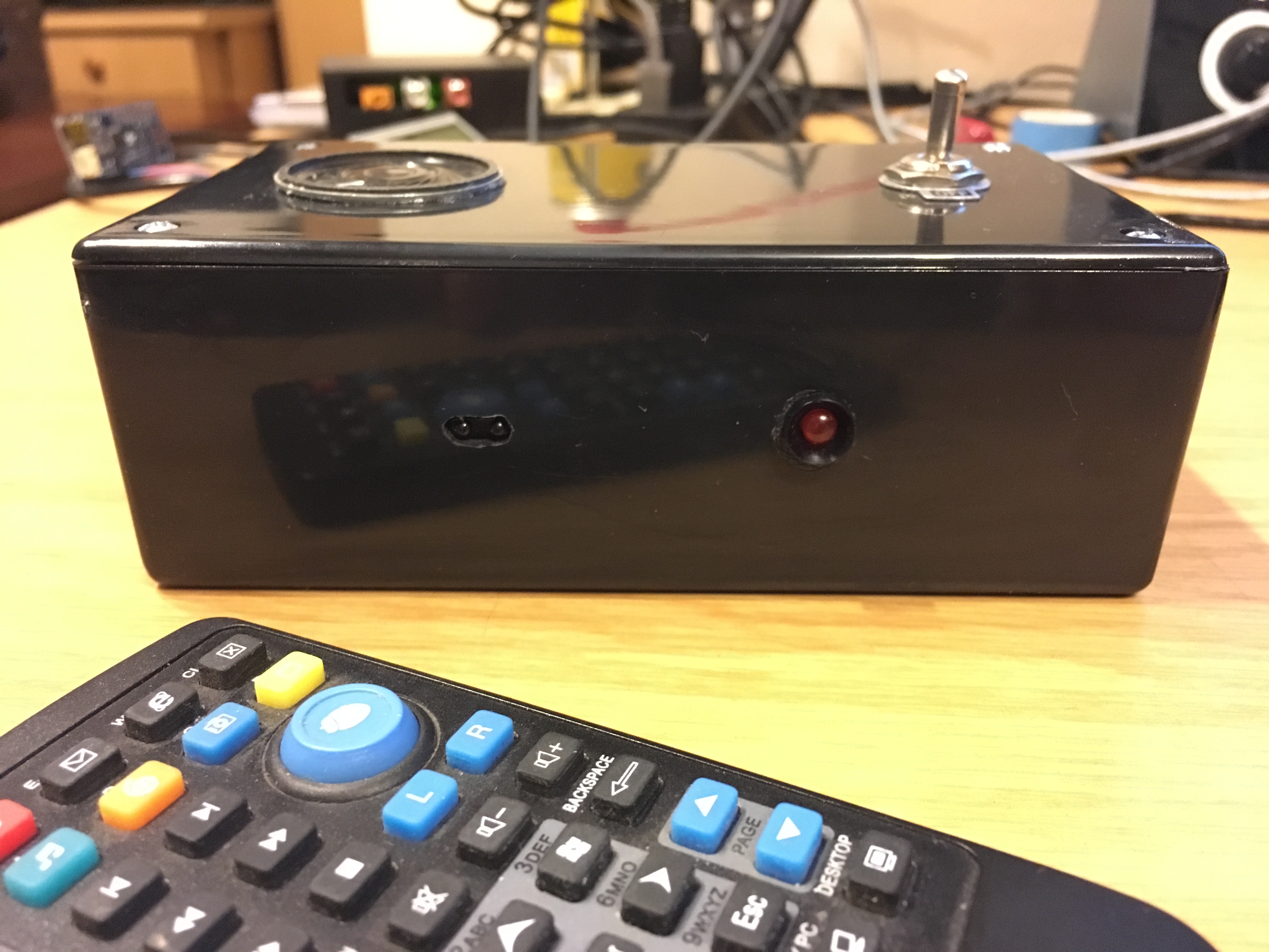
Finishing Touches
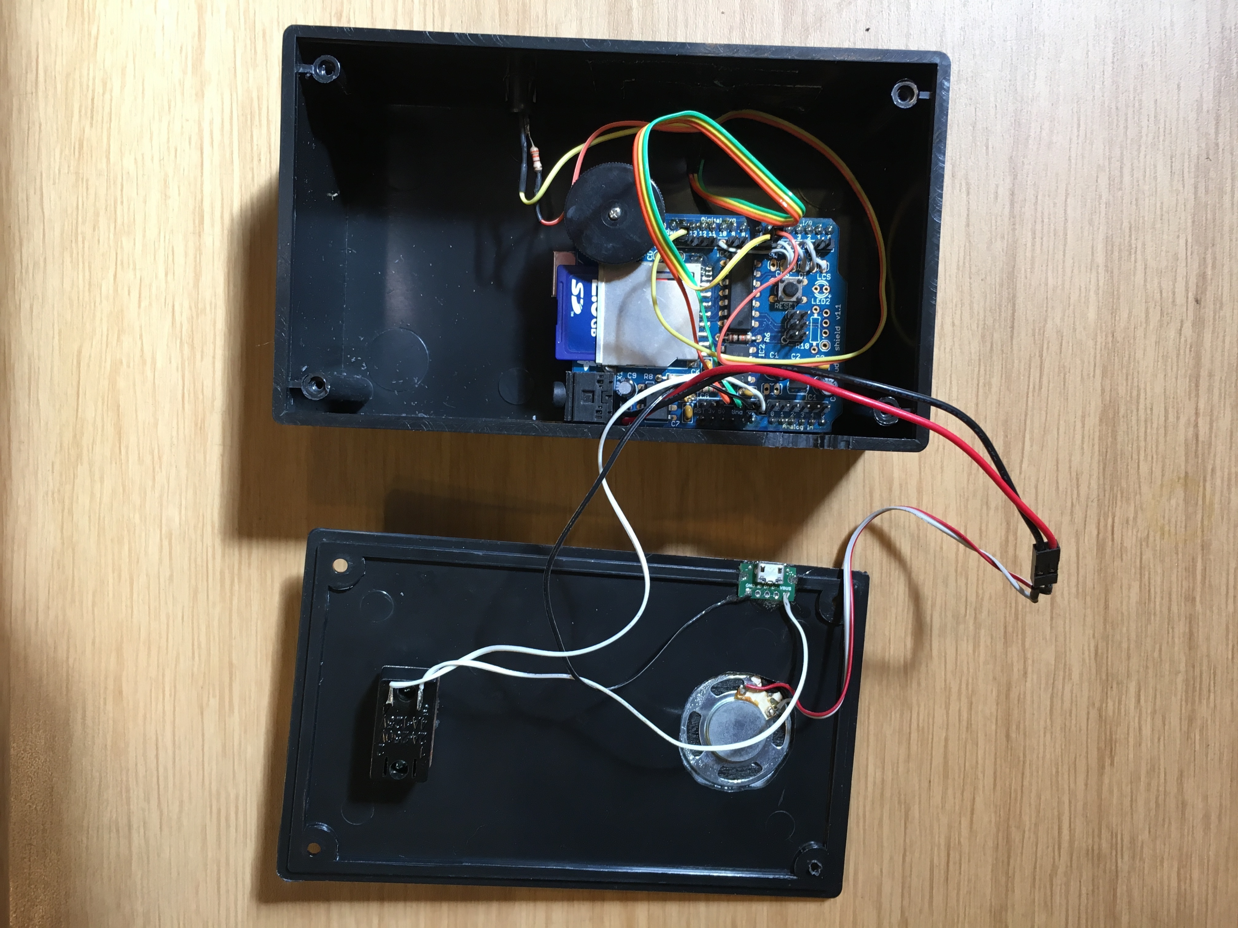
Enclosure
I used a spare black ABS plastic enclosure I found in one of my drawers. I used a Dremel to (not very neatly) cut out holes for the toggle switch, LED, IR receiver, micro USB breakout and speaker.
I used double sided tape to secure the Arduino + Wave Shield to the bottom of the enclosure.
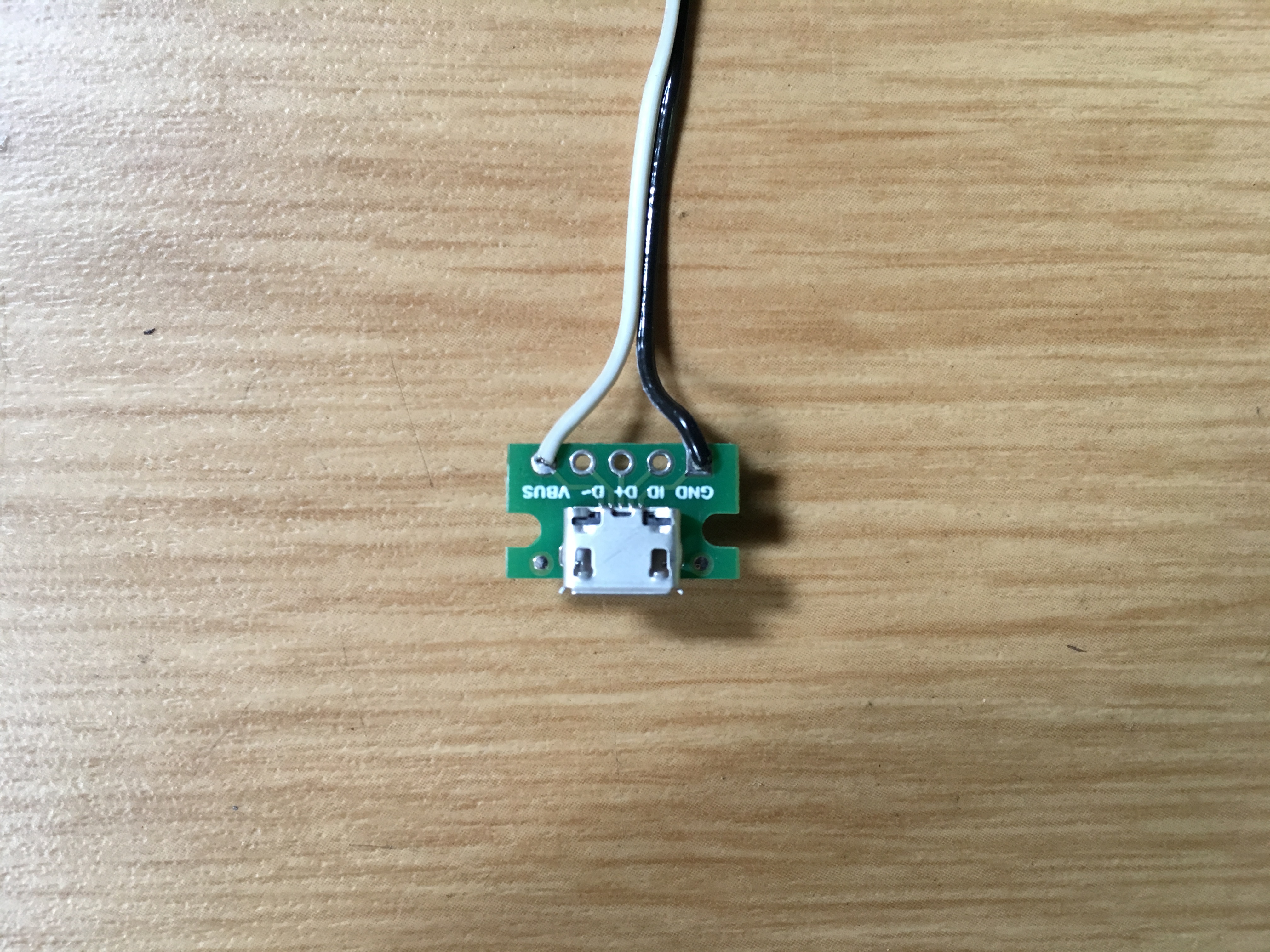
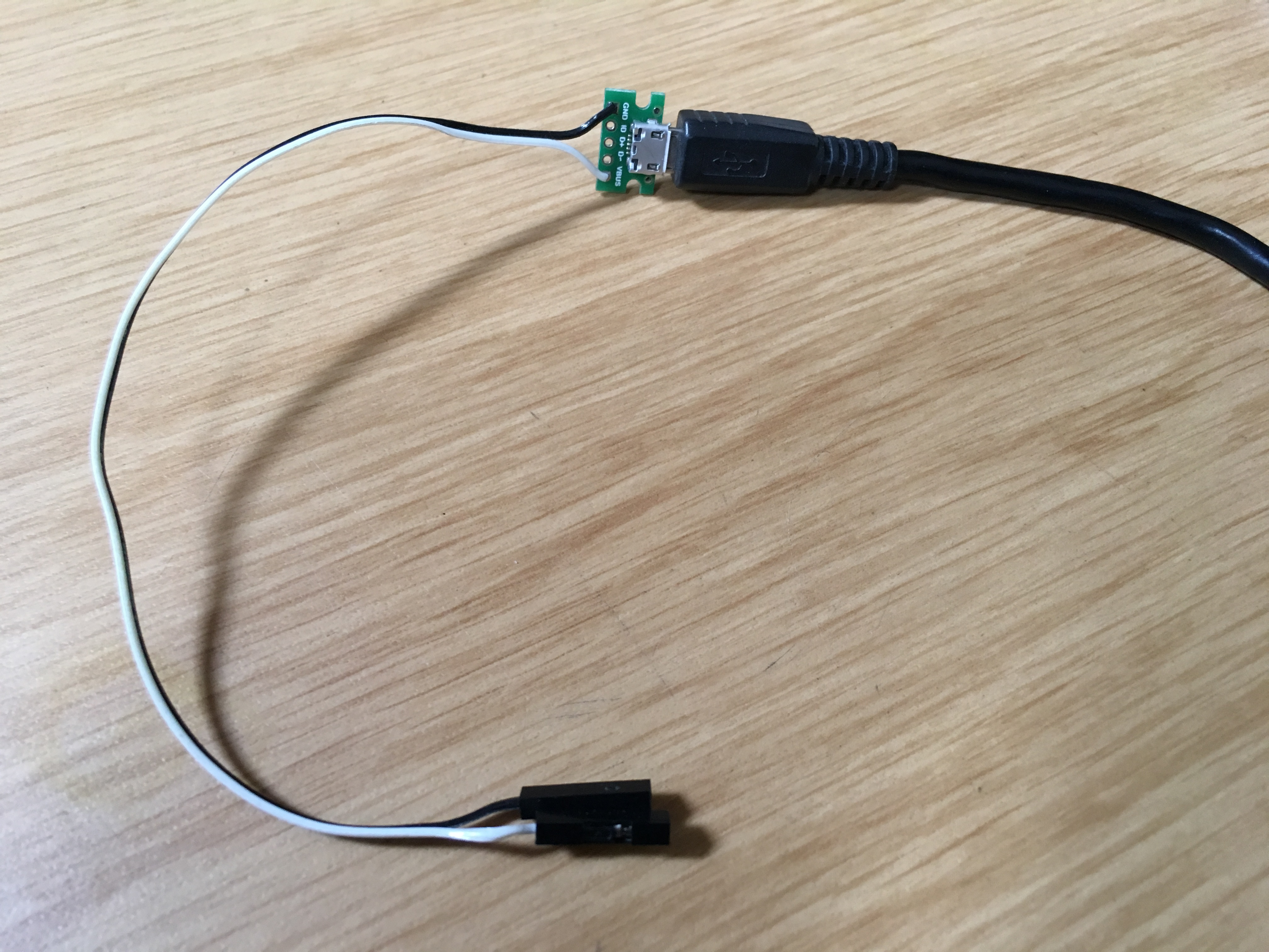
Micro USB Power
I decided to provide 5V DC to the Arduino via a micro USB connector breakout board. I have tons of micro USB cables and USB power supplies from various devices lying around, and this also means less cutting into the enclosure than I would need to in order to expose either the Arduino’s barrel jack or the large USB type B socket.
I soldered some coloured ribbon cable to the breakout, and then added some female header connectors so they can plug straight into the exposed header pins of the Wave Shield.
Toggle switch
I used a single pull, single throw toggle switch inline with the 5V from the micro USB breakout to switch the Arduino on and off.
Activity LED
The activity LED is a 5mm red LED connected in series with a 330 Ohm resistor to one of the Arduino’s digital pins.
Arduino Pins
Here is a rundown of the Arduino pins used, excluding the ones used by the Wave Shield:
- Vin: 5V from Micro USB breakout (via toggle switch)
- GND: GND from Micro USB breakout
- GND: to IR Receiver GND
- 5V: to IR Receiver Vcc
- Digital pin 7: to IR Receiver output
- Digital pin 6: to red activity LED anode
- GND: to red activity LED cathode
Conclusion
I’m really happy with this build. I use it every night, it definitely helps mask out the noise in my head as I lie in bed trying to fall asleep (or trying to wake up!).