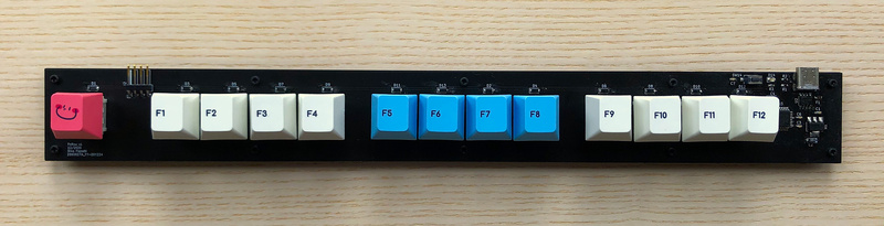
FnRow is a mechanical keyboard I designed and built during the Christmas break. It features a single row of switches in the form of a “function row”. Each switch is configurable and can be programmed to perform as any key on a typical keyboard, or even combinations of key presses. FnRow is akin to a “macropad”, but instead of having a square or rectangular “pad”, the switches are stretched out in a single row. All my hardware and software source files are available on GitHub.
Features
FnRow was designed with the following features in mind:
- Cherry MX footprint compatible
- USB-C connectivity for data and power
- USB ESD and over-current protection
- QMK programmable
- VIA compatible
Motivation
I have been a long time mechanical keyboard enthusiast, and I tend to rotate out my “daily driver” keyboard every few months. Currently I am using a keyboard which makes use of a “60%” layout. This means that the keyboard contains around 60% of the keys of a full-size keyboard. It has no function row, or arrow keys, or numpad. This sounds like a pain, but for the most part I really like the small form factor. It’s light and easily transportable and takes up very little space on my desk.
To activate one of the missing keys on this keyboard you have to make use of a designated key in combination with one of the available keys. For example if I wish to activate the “F7” key on my 60% keyboard, I have to press and hold the left “Windows key” down, and then press the number “7”. This keyboard uses an HS60 v2 PCB which already supports smart features like assigning key combinations to other keys (and supporting multiple layers for each key), but unless you want to lose functionality of an existing key you always have to first engage the special/modifier/layer key to engage a missing key.
I really enjoy using keyboard shortcuts in my work, mostly for launching applications, navigating through workspaces, and for navigating and activating features within my IDE. With a small form factor keyboard like mine it can be a bit of a challenge to generate key combinations that are required for doing some of these activities, e.g. “Ctrl+alt+shift+F6”. Yes I could map that combination to a “special key + ” on my HS60… or I could use a dedicated single key from a macropad. That I built myself. In the weird form of a single row of keys.
That’s the formal justification, but really I just wanted to be a nerd and build my own keyboard during the Christmas break.
Hardware
Function Row Form Factor
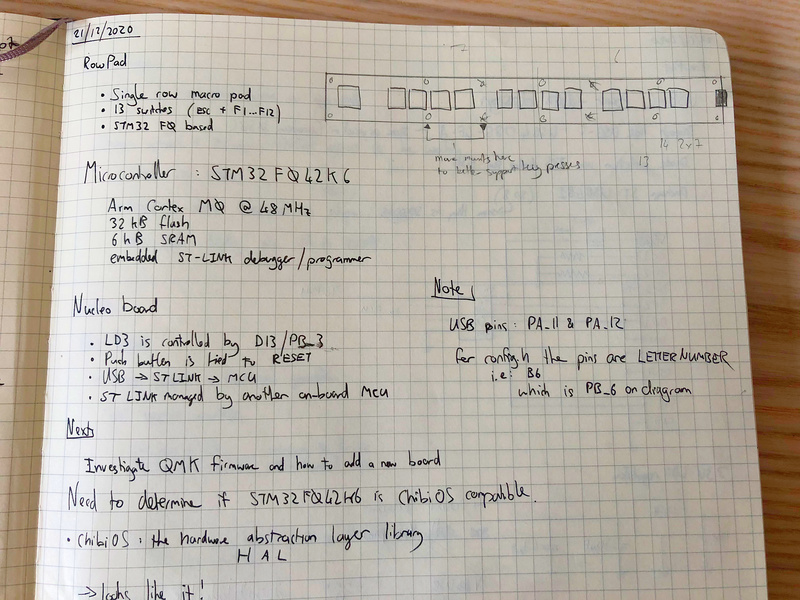
There are currently many existing configurable macro keyboard options, some pre-built and others available as kits. The keys are typically arranged in a rectangular “pad” configuration, hence the name “macropad”. I wanted my design to be different yet familiar, and so I chose to arrange the keys in a single “function row”, hence the name “FnRow” (it was actually originally titled “RowPad” before I realised that was a bit of a contradiction). You can see my initial idea and sketch here:
Microcontroller Selection
I knew I wanted the keyboard to be QMK compatible. QMK is a firmware project which makes it really easy to program microcontrollers (MCUs) with keyboard functionality. I wouldn’t have to do any low-level programming, just set up a few build rules and configuration options, and QMK would generate the microcontroller firmware for me. Do I feel guilty for not crafting the firmware myself and obtaining a profound understanding of how USB HID works? Nah. That’s another project, for this I wanted to have fun building a working keyboard relatively quickly.
So looking at the QMK docs I saw that the recommended microcontroller platform is STM32. While I have experience working with Microchip PIC and Atmel AVR MCU families, I had never used an STM32 chip before, but looking at the requirements for QMK I determined that I needed an STM32 MCU that supported USB and had 32 KB of flash memory. I decided that I should probably use a development board for a basic prototype before ordering PCBs and components. ST provides various “Nucleo” dev boards, and looking at the capabilities matrix it looked like the STM32F042K6 was the MCU that most closely matched the minimum requirements (I didn’t feel the need to go overboard on MCU features).
It was at this point while doing research on custom keyboards built using the STM32F042K6 that I came across a truly enlightening blog post by Jayden Meyer titled “Building a Macro Keyboard” which detailed how he built a macropad keyboard by first prototyping using a Nucleo dev board and then designed and built a custom PCB! This post was extremely useful throughout my own project. Thank you Jayden! My project differs to his where he actually did program the MCU with his own firmware to send out specific keycodes over USB, whereas I am using QMK to compile the firmware using a custom configuration, and VIA to support modifying the key mappings without needed to reflash the MCU, as well as USB connectivity choices and protection.
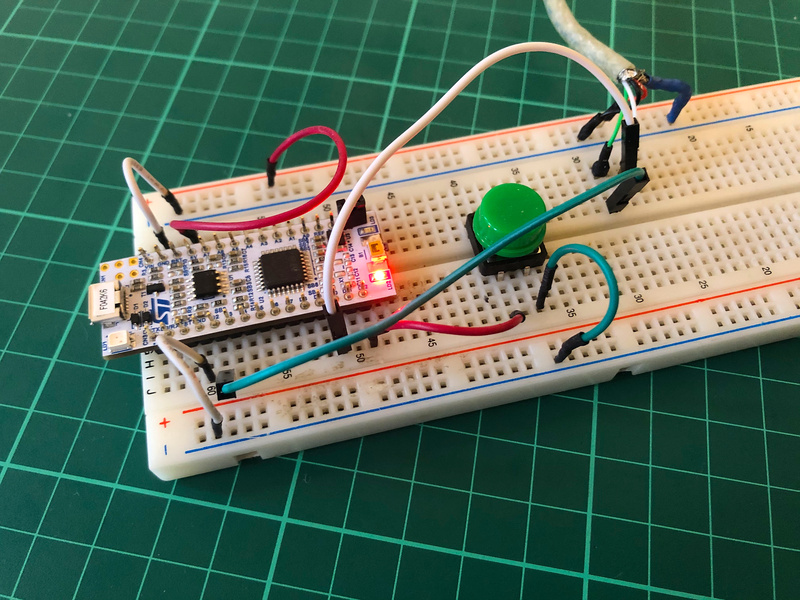
Prototyping
Once the STM32 board was delivered I followed the QMK tutorial to set up my laptop for QMK development. Using bits and pieces of existing keyboard projects within the QMK source, in addition to the guidelines I then compiled a simple single key keyboard using QMK, and flashed it to the device. Doing this gave me confidence that my local QMK dev stack was working. I didn’t see any further complexity in increasing the number of switches, so once this was working I moved on to the creating the FnRow v1 schematic and PCB layout.
Schematic and Components
KiCad source files are available in the FnRow GitHub repository.
I used KiCad EESchema to develop the schematic:
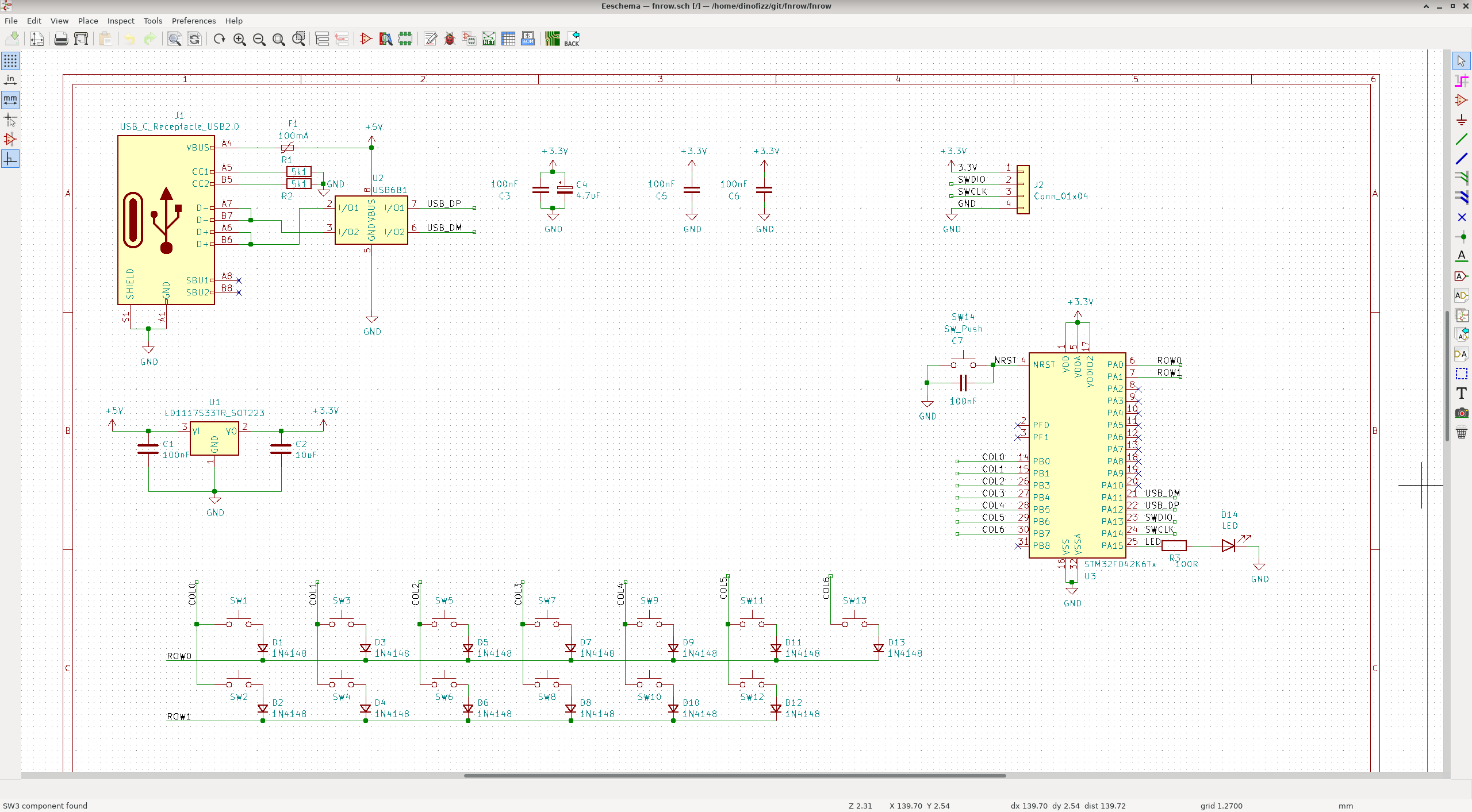
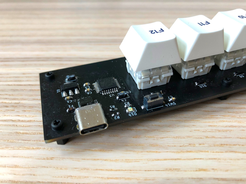
USB Protection
I wanted to do something a little bit more thoughtful than just running the USB traces directly to the MCU, and so added two protection features:
- USB ESD and over-voltage protection using the ST USB6B1 integrated circuit.
- Over-current protection using a re-settable fuse.
3.3V Power
I’m using a pretty standard low drop-out linear regulator, the LD1117v33 to convert the 5V from the USB bus to the 3.3V that the MCU requires.
Other features
The other two custom features I added was a dedicated MCU reset switch and a status LED. The reset switch makes it easy to place the MCU into the default STM32 bootloader mode for flashing new firmware, and the status LED indicates the QMK start-up status by providing an initial “blink”.
Switch matrix
While I technically have enough pins available on my STM32 MCU to dedicate each of my 13 switches to their own MCU pin, I did want to get “practice” in creating a switch matrix. Using a switch matrix is a common pattern in custom keyboard designs as it minimises the number of pins required for reading the switches. The switches are broken down into a ROW and COLUMN matrix, with the firmware cycling through each possible matrix position one at a time to determine if the switch at ROW x and COLUMN y is currently de-pressed or not. The QMK docs explain this in more detail. I broke up my single physical row of switches into 2 logical rows and 7 columns, so instead of needing 13 pins to read all my switches, I only needed 9 pins.
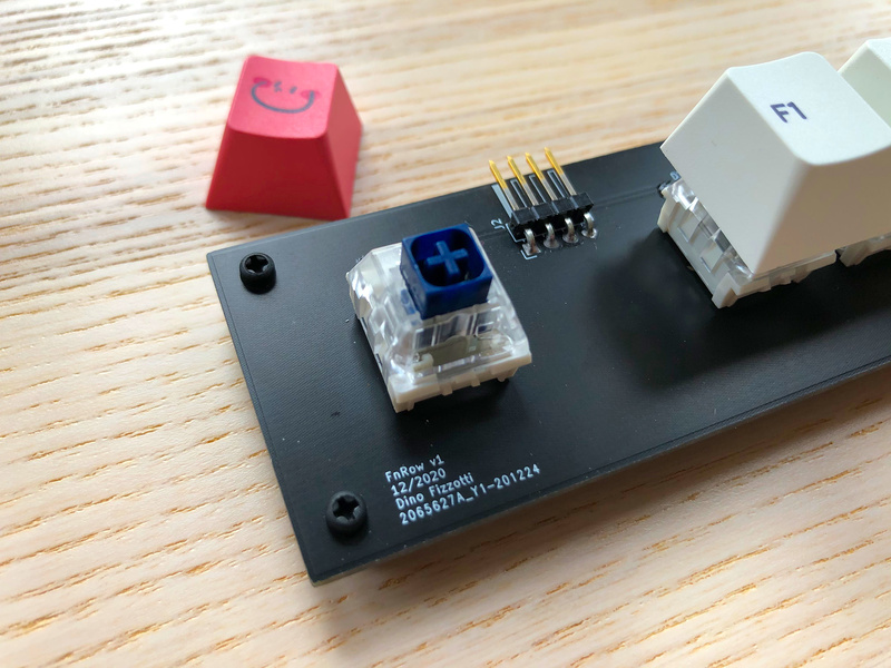
Serial Wire Debug (SWD) interface
With the STM32F042K6 it is possible to use USB to program the device using the default bootloader, but I thought I would add an additional firmware flashing interface - Serial Wire Debug (SWD) - which as the name suggests also supports in-circuit debugging.
PCB Layout and Manufacturing
KiCad source files are available in the FnRow GitHub repository.
I used KiCad PcbNew to layout a 2-layer PCB. I opted for a surface-mount component selection to minimise the physical space required for components on the PCB. The only through-hole components are the SWD headers and my choice of USB-C connector. A surface mount USB-C connector would have been more difficult to solder by hand. For the passive components I didn’t go smaller than the 0603 footprint.
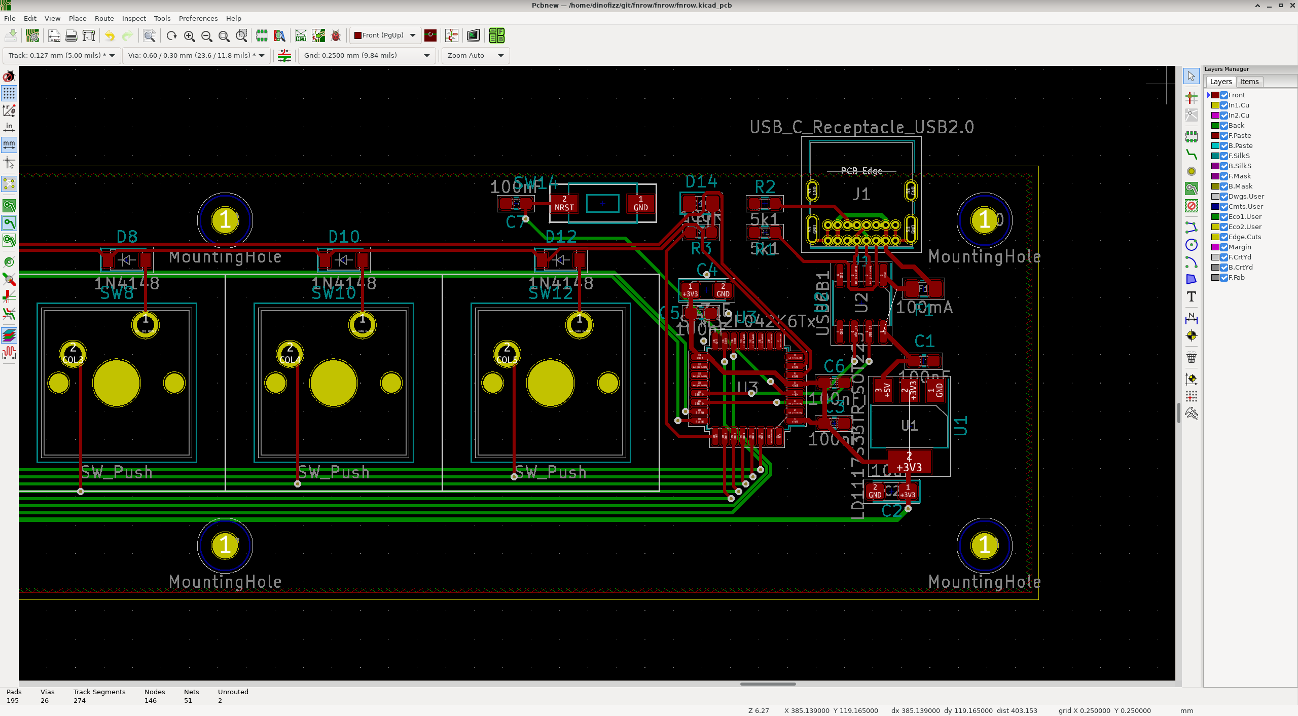
It was my first time doing PCB layout in a few years. I made sure to include some of the obvious features - keep the decoupling caps as close as possible to the ICs, and use thicker widths for power than for signal traces. In hindsight I could have done a bit better on some of the routing and sticking to best practices, but I was too excited to get it done. If I do a v2 I will be sure to include some layout improvements.
I used JLCPCB for PCB manufacture, as I had read some good reviews by others. I submitted my order on 23 December, it was released by JLCPCB on 27 December, and delivered to me on 7 January via FedEx, which I didn’t think was too bad given the current situation with COVID-19 and this being over a holiday period.
Bill of Materials
You can find the interactive bill of materials for this project here (generated using the InteractiveHtmlBom KiCad plugin).
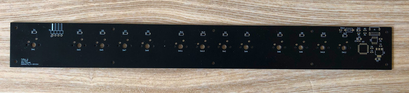
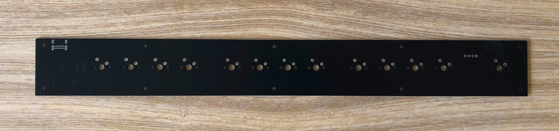
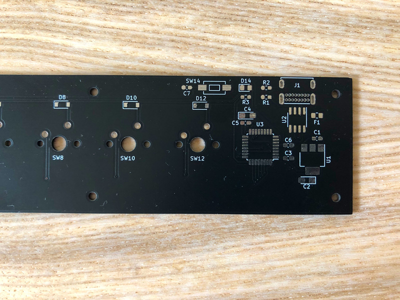
Assembly
Here’s what the boards look like before installing the components:
I added a bunch of flux to help with the fine pitch components, which is always a pain to clean up afterwards. I practically drenched the board in isopropyl alcohol, but there are still some sticky patches around the MCU. I was always told to avoid the “no-clean” flux as it wasn’t as good as the sticky stuff.
In another instance of hindsight I should also have opted to have made use of JLCPCB to do the surface mount component assembly. I didn’t have any problems with doing the soldering by hand myself but JLCPCB’s SMT assembly option only adds a few dollars to each board. I do think owning a microscope would make things easier - I think 0603 passives are as small as I can solder without one.
Firmware and Software
Blink the LED Test
Before jumping in to flashing the QMK firmware I decided to test that the MCU was running OK after assembly with a simple LED blinking program. I made a fork of Jayden’s STM32 blink test project and modified it to work with my specific configuration. Once compiled I decided to also test my SWD interface and used an “ST-LINK V2” clone to flash the firmware to the device.
This confirmed for me that the MCU was operating as expected.
QMK
I then created my own dinofizz/fnrow/v1 directory with in my fork of the QMK code and set up the required files as per the guidelines. You can see all the changes I made in in my fork of the QMK project here.
A big help was doing a grep in the qmk_firmware/keyboards folder for other keyboards using the same MCU as me - the STM32F042K6. In this way I had a few references which helped me put together the correct values for my own config.h and rules.mk files.
VIA
VIA is a desktop tool which lets you reconfigure your keyboard without needing to flash new firmware.
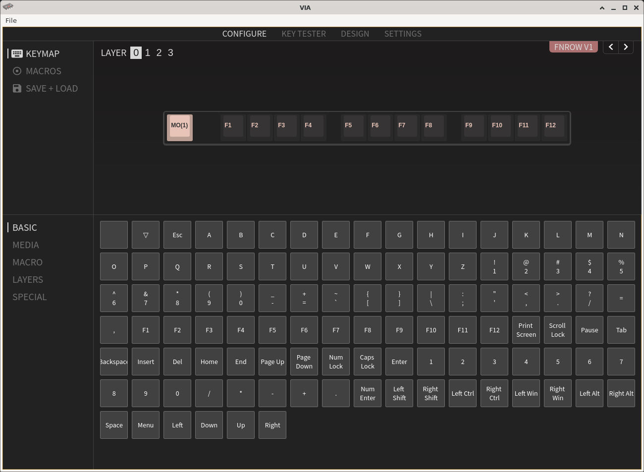
With VIA I can map different combinations of key presses to one of my 13 FnRow switches. With the use of special keycodes assigned to specific switches in the base layout I can assign switches in up to 4 different layers. This means that I can press switch 13 and have it act as F12, or press and hold switch 1 (Layer 1 modifier) and then switch 13, to activate switch 13’s Layer 1 key. As I have used VIA to map switch 13 on Layer 1 to “Prnt Scrn”, this key combination of switch 1 + switch 13 will launch my screenshot tool.
Enabling VIA support for the FnRow required a small config change and an additional keymap in the QMK code, and then creating a VIA layout JSON. You can see my layout file in my fork of the VIA project here here.
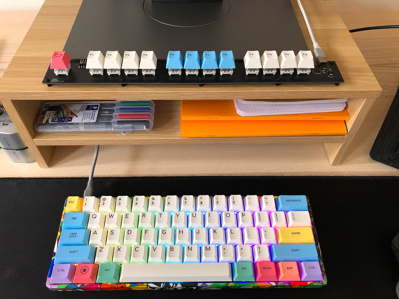
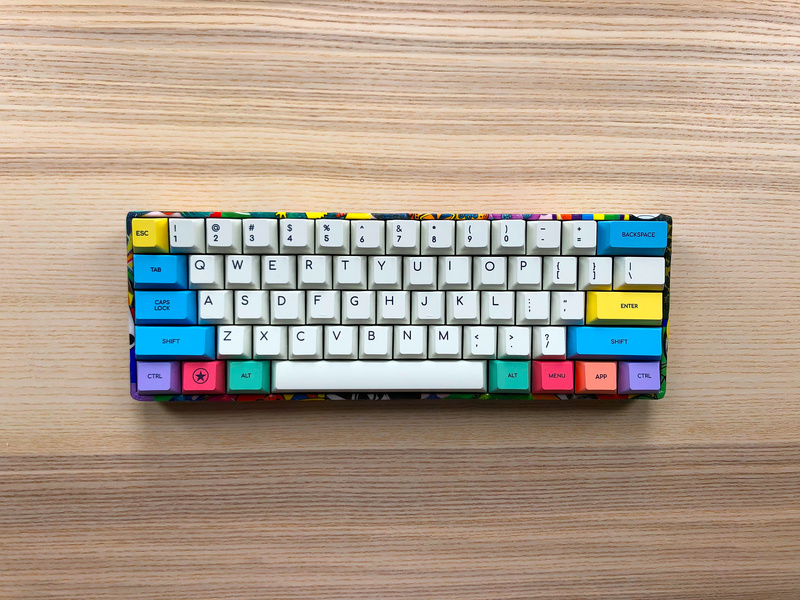
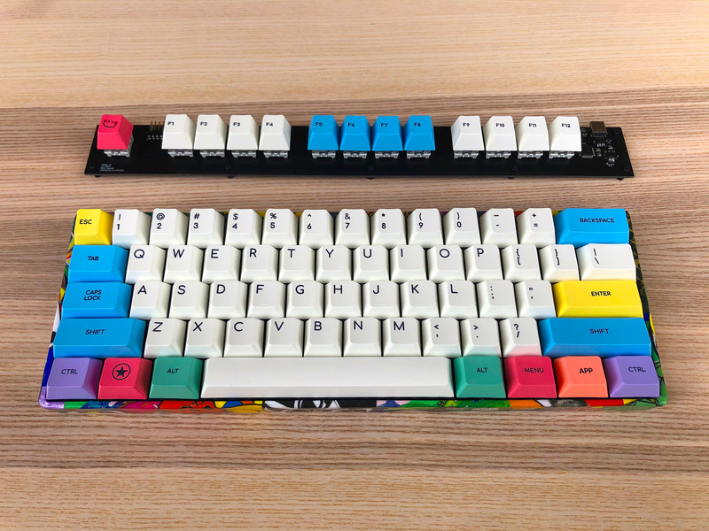
Switches and Keycaps
My 60% keyboard uses 78g Zilent V2s, which are very tactile, but as the name suggests, relatively quiet. I wanted something clicky for the FnRow, so I bought some some “Thick Click” NovelKeys\Kailh BOX Navy switches. They are SO good. They have a really great feel and a satisfyingly audible clickCLACK! sound. While the occasional clickCLACK! now and then is tolerable, I wouldn’t dare fill out my 60% board with these switches. My wife and I work from the same room - I might as well use the keyboard to type out the divorce proceedings.
As for the keycaps, well I just used the leftover F row keys from the set that I am using on my 60%, the Cherry profile “Chalk” set from KBDFans.
Conclusion
This project was a great way to spend some of my Christmas break. I am really impressed with the QMK and VIA projects, they make building custom keyboards really easy. In total I spent 1 day on prototyping with the STM32 Nucleo board and figuring out how QMK works, 1 day on schematics and PCB layout, 1 day on double checking everything and ordering the components, and then a half day to assemble and flash the firmware.
clickCLACK!